Interactive solution
for geometry reconstruction (”reverse engineering”)
Harald Eckert / Nov.
98
1. Preface
In the area of more powerfully becoming
construction and visualization systems, in which either is three-dimensional
designed and/or large quantities of 3d geometry as shaded image are represented
(e.g. Digital MockUp - digital display
model), exist a large requirement of processing of old information,
in order to be able to operate also at the modification of old devices
(e.g. conventionally designed airplanes) with
most modern construction systems.
NC-measuring machines, video technology
and different laser technologies enable
the 3d digitizing. For the moment one looks for possibilities of
generating from a cloud of points developing
thereby as high-quality a geometry as possible
(e.g. CATIA-Solid-E with CSG(Construktive Solid Geometry) - tree,
STEP advanced boundary representation).
From the experiences, which the author
made in the context of a CAD project with the so called "intelligent digitization"
in the 2d area, a suggestion will be made,
as by interactive connecting of 3d digitizing, simple surface recognition
and a construction system an optimal working
process for the geometry reconstruction
("reverse engineering") can be arranged.
2. Intelligent 2d digitizing
The pending function consisted of the fact
that some thousand "2d copying templates", which were used to cut the raw
material for the production of airplane sheet metal bending parts,had to
be transformed into analytic geometry, which were necessary for programming
a numerical controled machine tool.
With the "intelligent 2d digitizing" consciously
the automatic producing of a cloud of points by automatic tracing the contour
was eliminated.
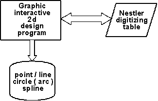
Rather became a graphically interactive
2d NC programming system, which was operated by means of a ADAGE 4250 scope
attached to a IBM MVS computer, interconnected with a Nestler digitizing
table as follows:
-
At the Nestler digitizing table the digitization
magnifying glass was replaced by a swivelling measuring cut, with which
the outer contour the "2d copying template"
could be touched.
-
The loadable Microcode of the Nestler digitizing
table was programmed in such a way, that a 6 byte long information could
be transferred to a serial interface, if one of the control keys
were pressed.
-
The 6 byte long information contained beside
the 2 byte X- and Y-coordinates also of specifications
concerning the pressed key, with which additionally to the built-in function
keys the program flow of the 2d NC programming system could be
influenced.
-
Over a interface devices operating into the
internal data bus of the ADAGE 4250 and a changed Microcode of the ADAGE
4250 the 6 byte could be put into the 2d NC programming system. (at the
transition to IBM 5086 scope the same
was managed by means of a serial port, which was operated as
a additional graphic address).
With this combination the following mode of
operation was possible:
-
The template to be digitized was fixed on
the Nestler digitizing table.
-
The position of the x axis and the coordinate
system origin was determined by measurement of 3 points.
-
For the geometry definition in the 2d NC programming
system required point data were consulted by the Nestler digitizing table,
whereby the most important function keys (POINT, LINE, ARC, CIRCLE) could
be pressed from Nestler digitizing table.
-
For check additional points could be measured,
read into which 2d NC programming system and compared with beforehand produced
geometry.
The advantage of this mode of operation consisted
of it that
-
a genuine reconstruction of geometry could
be executed,
-
comparatively few expenditure had to be operated
and
-
violations apparently happend when using the
templates did not appear in the reconstruction result.

3. Interactive 3d digitizing
Similarly to the "intelligent 2d digitizing"
the "interactive 3d digitizing" should be a type of "reverse
engineering" -- i.e. determining high-quality a geometry (CSG - Constructed
Solid Geometry, volume, surface, curve, point) from 3d measuring points
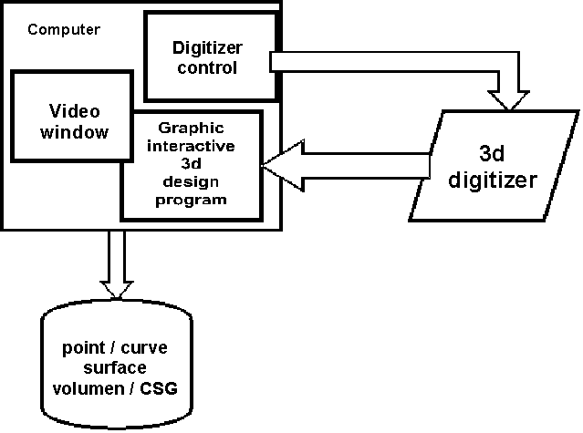
-- , which combines on a workstation the following components :
-
3d design system (e.g. CATIA)
-
3d digitizer (e.g. coordinate measuring machine,
3d laser scanner, 3d picture investigater, ...)
-
Control window for the 3d digitizer
-
Video picture of the object, which is be digitized

The arrangement shown should enable the
digitization and transformation of measured geometry (points, polygone,
point samples) into geometry with higher order (curves, surfaces, limited
surfaces) and the following assembly to structured volumes in one processing
step.
Advantages:
-
The point quantity which can be measured can
be drastically reduced.
-
The surface allocation of measuring points
is problem-free, since the measuring points are processed immediately in
each case.
-
In the 3d digitizer higher functionality (e.g.
rule geometry recognition) can be carried out.
-
Manufacturing or use-conditioned irregularities
of the digitization object can be eliminated.
-
Rational combination of digitization and reconstruction
of component geometry.


